As the first homes of Anthology’s Hoxton Press are being sold, we reflect on the invention and design of the brick soffit solution which was used as cladding for this development. We asked Project Director Jim Watts from Wates Construction Ltd, the lead contractor on this project, to explain the process they went through from design to installation.
The Architects, Karakusevic Carson Architects and David Chipperfield Architects, had envisaged a pre-cast concrete panelised system for cladding the building with bricks embedded into the face of the panel. However, this system was proving too heavy for the building’s structure. Given this and the uncertainty on price that we were receiving from the PCC manufacturers, the project needed an alternative solution. In conjunction with our Engineering Department and long term supply chain partner Swift Brickwork, we started to explore switching the design to a traditional wet lay brick solution. Whilst this was relatively straight forward for the facade elevations, the large balcony soffits were an entirely different proposition. We needed a system that would look like traditional brickwork but would effectively be hanging approximately 150mm lower than the structural slab above. Given that we would be installing the soffits 20 floors up during the damp, windy and cold English winter, we didn’t want a system that relied on adhesives when working in tension.
Mike Walsh (Joint MD of Swift Brickwork) introduced us to the owner of his long term supply chain partner Colin Pinnegar of Bulmer Brick Cutting Services. Colin had at that stage an idea of a secure brick rain screen / soffit solution that was mechanically fixed.
Given the size of the project and the ‘then’ current manufacturing facilities that Bulmer had we, along with Swift Brickwork, assisted Bulmer in up-scaling their premises and machinery to cope with the requirements of the project. Bulmer now has a first rate manufacturing facility with trained operatives and management who understand the need for quality control and the careful selection of bricks with regard to texture, size and colour.
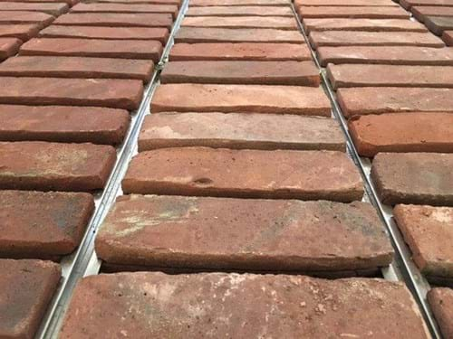
The system is now being marketed as SafeSecure Reinforced Brick Cladding. Essentially it is a backer board that has brick slips adhered to it, but with the addition of a stainless steel top hat section channel picking up the brick by way of a grove in the side of the brick slip. The channel is then bolted into the supporting structure either horizontally or vertically. Following installation, the joints can then be pointed in with mortar.
Safe Secure Reinforced Brick Cladding
Colin Pinnegar developed the system in response to an opening he identified in the market; in particular, the bad press around brick slips falling off buildings when only glued to soffits, lintels and similar features.
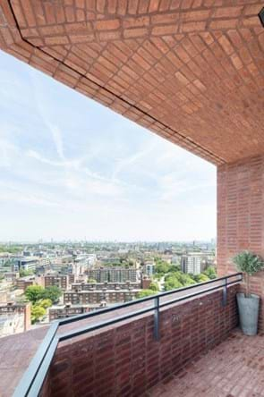
Essentially we manufactured the panels with ease of use in mind - easy to pick up and manoeuvre - but with an aim of maintaining the aesthetics. For the balcony soffits we made the panels 2 bricks wide and the width of the balcony. To make the workface safe for the operatives working at height we manufactured a scaffold bracket that was fixed to the permanent handrail support. This allowed us to work safely, dress a monarflex screen to deal with any potential of falling materials or equipment without adversely affecting the brickwork walls or permanent handrails. The soffits were loaded onto aluminium scaffold towers and bolted through the stainless steel channel in the panels and onto the stainless steel sub grid of supporting structure immediately below the concrete soffits. We left ventilation strips with SS fly screen in front of the windows. We also formed an open movement joint between the soffit system and the main elevational brickwork.

As a responsible design and build contractor we have an obligation to the home owners, our client and the community to make sure that what we leave them is robust and serviceable. What is referred to as an invention when you’re desperately looking for solutions to fulfil an architect’s vision can all too soon be referred to as “you cobbled some things together”. We needed to be sure that a brick suspended on a soffit 20 floors up would stand the test of time. To that end, Bulmer resourced a testing and accreditation service that could carry out the testing in the time frames we needed. Given how busy the Test Houses in England were, Bulmer had to go to KIWA BDA - a global test body based in Holland. There, the system was subjected to all the usual tests of wind, heat, rain, cold, fire, etc.
Bulmer obtained "BDA Agrément BAW 18-068/02/A" certification. During installation we also had our Group Chief Engineer John Rivett review the system and to add further risk management we employed Eckecksley O’Callaghan for a peer review. All were satisfied and it has been a great success that has enabled us to fulfil the Architects’ vision in a manner that is buildable and safe to install, will stand the test of time and will look terrific for at least the design life of the facade. You cannot beat a brick for longevity of appearance.
Given that the soffit solution was such a success we adapted it to form the ground floor brick vaults, or half vaults to be more accurate. Again, the Architect had envisaged utilising a pre-cast concrete solution to enable this. However, this gave us both programme and logistical issues -each panel would have been in excess of 9 tonnes in weight and we would have been trying to install them under the first floor concrete slab. As a result, Swift and Diva Architectural Metalwork came up with a lightweight solution which could easily be transported on our congested site. Diva laser cut the corner beams to the 3 different radiuses, as per the Architect’s vision, fabricated them into box sections and then run straight steels between them. This gave us a true curve that, provided we kept level, couldn’t go wrong. Given the uncertainty of movement within this arch we used lime mortar in the brick joints for the added flexibility.
Working with Wates was a joy, nothing was too much trouble and they responded quickly to my queries carrying out remedial works where necessary. They had an open and honest approach making it very easy to work together. I was particularly impressed when they decided to invent the brick slip solution for the scheme – the final product looked like realistic brickwork, showing off excellent workmanship.
Note: Anyone proposing to use this system should check its suitability for the location and type of building having regarded all required performance standards.
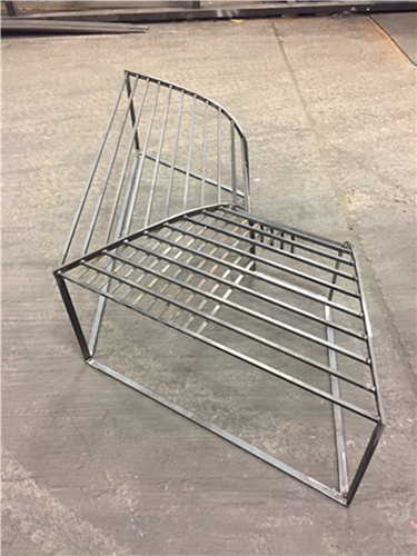
Scaled model of the steelwork for visualisation and discussion.
First section fabricated at Diva’s factory
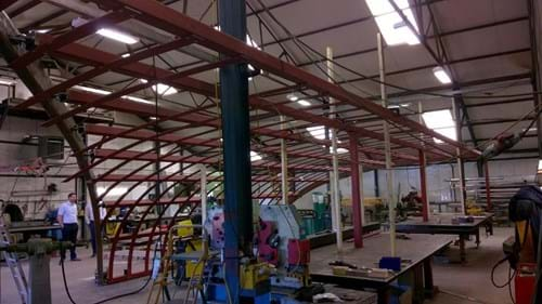
Making sure that the geometry of the steelwork setting out gave us the correct aesthetic at the corner junctions, before we produced all the steelwork and arrived on site.

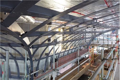
Vault steelwork in place and Safesecure panels being fitted.
Finished Vault.

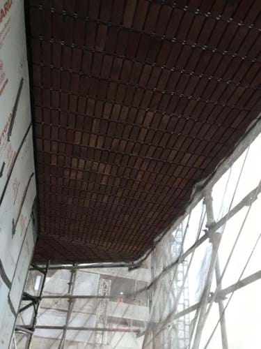
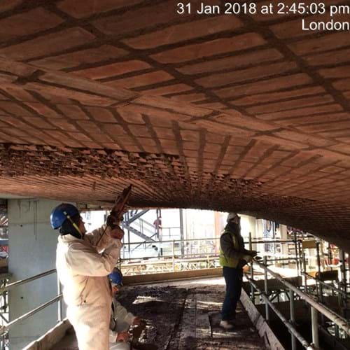
Pointing up Safesecure soffits.
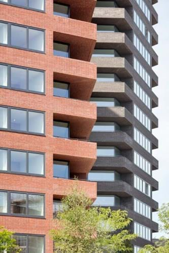
View of finished building