Download a PDF version of this article.
This guidance provides information to designers, developers and surveyors to assist in meeting the functional requirements of the Premier Guarantee Technical Manual where a balcony is proposed on a project covered by our warranty.
This document includes:
A balcony is a building component which is an accessible external amenity platform above ground level which is exterior to and with direct access from a building. A balcony can project beyond the walls of a building; it can be formed within a recess of a building; or it can be a hybrid of both as further explained below. A balcony does not form part of the thermal envelope, e.g. not forming a roof. This guide relates to balconies and not terraces and the guidance relating to roofs in the technical manual should be followed where a ‘terrace forming a roof’ is proposed.
Projecting balcony
An accessible external amenity platform affixed to the exterior of a building above ground level exterior to and with direct access from a building.
Enclosed balcony or inset balcony
Accessible external amenity platform that is protected from rain ingress by a roof or balcony above and a wall(s) or weather screen to the sides.
Semi-inset balcony
An accessible external amenity platform affixed to the exterior of a building which is in any way set back into the main wall line or thermal envelope of the elevation. Where this forms part of the thermal envelope the designer will need to for the purposes of the drainage design consider this to be a roof terrace.
Roof terraces
A roof terrace is a roof with general pedestrian access. It may form a floor which may be utilised for use and enjoyment of amenity or maintenance activities. A terrace is a roof for the purposes of waterproofing and the design of waterproofing and drainage. Guidance in the technical manual relevant to flat roofing should be followed to meet the relevant functional requirements.
Attention should be drawn to regulations regarding combustibility for the outer weather screen in terms of The Building (Amendment) Regulations 2018, Regulation 7(2).’ e.g. laminated glass/ fire tests for systems.
Winter Garden
An enclosed balcony is sometimes referred to as a “Winter Garden”. Due to the variation in levels of enclosure these can be in some cases considered a habitable room and care regarding the assessment of key criteria such as structural robustness, escape from fire and potential fire spread, condensation risk and moisture penetration, acoustics, ventilation, heating and cooling, protection from falling and safe breakage including appropriate glazing specifications, thermal performance and accessibility will need to be assessed on a case by case basis.
The guidance is not prescriptive and provides an outline as to approaches which when considered on a site specific basis may be deemed acceptable and following the guidance provided, the project team must be aware that it is not a guarantee of acceptability in its own right.
This update will provide technical guidance regarding the common types of balconies and the key risks to consider in the design and strategies to overcome those risks.
This guidance focuses on buildings which has: six storeys or greater, rather than buildings that have a storey height greater than 18m as defined in Diagram D4 of Approved Document B: Volume 1.
Also:
Drawing submission
As a minimum, the design team should prepare the following drawing for review:
Meeting building regulations
The designer must ensure that requirements relating to all building regulations are achieved. The designers attention is particularly drawn to Approved Document A, B, C, E, F, H, K, and M in relationship to balconies and compliance with these requirements through the employment of the guidance in the relevant Approved Document or referenced guidance within that Approved Document when appropriately applied will tend to support a suitable design approach.
The developer and the builder must comply with building regulations and the authorised building control body involved inspects their work. In undertaking the inspections and performing their role, the surveyor is not assuming any duty or responsibility or assurance that the work has been completed to any particular standard.
Warranty limitations
The designer must be aware of the specific scope of the Premier Guarantee policy in context of the limitations of the Technical Manual guidance compared with additional requirements contained within other standards e.g. BS 8579: 2020, which may extend beyond the scope of our requirements. The designer may consider their own design, aims beyond the minimum requirements of the Technical Manual in any specification and in this instance BS 8579: 2020 may be consulted by the designer. The aim of this guidance is to highlight the minimum requirements relating to the design and construction of balconies against the requirement of the Technical Manual.
Weather tightness, upstands and fall
The key to the successful incorporation of any balcony is the detailing and construction of the interface with the building envelope. Upstands and comprehensive detailing ensure the building is protected from water ingress and the damaging effects of poorly controlled water.
Falls to a minimum of 1:80 are to be provided to all balcony drainage types to promote moisture migration. Where falls are created, screeds may be employed. Screeds might be of heavy or lightweight aggregate, and be cement or bitumen-bonded; the added weight of a screed increases deflection of the slab. The insulation value of a lightweight screed should be taken into account when assessing the risk of interstitial condensation. The recommended thickness of a cementitious screed-to-falls bonded to a concrete slab is 40 mm nominal (25 mm minimum at any point) and the construction of upstands should take into account the necessary thickness of the screed. For thinner, liquid based screeds such as Poly Methyl Methacrylate (PMMA) screeds may be considered for use with typically reduced thicknesses when compared with cementitious screeds but must be carefully specified and applied in line with the manufacturers requirements.
Structural durability
The structure of the balcony is considered part of the home and therefore the functional requirements relating to durability of the structure of a balcony will apply, namely:
The structure shall, unless specifically agreed otherwise with the warranty provider, have a life of not less than 60 years. Individual components and assemblies, not integral to the structure, may have a lesser durability, but not in any circumstances less than 15 years.
Resultantly, components transferring load from parts of a balcony to the main structure of the building should have a service life equal to that of the primary structure of the building which for the purposes of warranty. Care and attention is needed to check that protection coatings for lightweight construction are appropriately specified.
For example, hot dip galvanizing to BS EN ISO 1461 with a minimum average coating of 85μm on steel of 6mm or more thick has an average life expectancy of more than 50 years in the UK in low exposure conditions. Due diligence will need to be shown in material selection to ensure durability is appropriately specified.
Attention will be required in order to ensure that the materials used are suitable to achieve the intended lifespan. For example, materials should be suitably protected against corrosion, see ‘Appendix C - Materials, Products, and Building Systems’ of our Technical Manual for further information.
A detailed design will need to be provided to evidence that the balcony structure and its affixation to the main building will be suitably provided. A testing and quality assurance plan for fixings, including those related to the balcony should be discussed with your Major Projects Manager.
Wind and vibration
Lightweight support structures, such as free-cantilevered steel balconies, can be prone to vibration due to wind or people movement. Structural engineers must take account of potential vibration effects due to orientation or location of balconies.
For buildings taller than 50 m, or with unconventional (e.g. non-rectangular) layouts, or in close proximity to other tall buildings, net wind pressures on guarding should be determined through detailed scale-model wind tunnel tests in accordance with BS EN 1991-1-4, its UK National Annex, NA to BS EN 1991-1-4, and PD 6688-1-4. Where glazing is provided, wind load calculations should be provided prior to glazing design’ for any building height/coastal location.
Fire safety
It is noted that national variances in building regulations exist across the UK. The overarching principle is to engage with the building control body relevant to that nation to ensure that the building regulation requirements are met. It is recommended as a starting point that the designer is to ensure that any constituent materials of the balcony contains materials of European Classification A2-s1, d0 or A1, classified in accordance with BS EN 13501-1:2018 unless directed as exempt under Regulation 7(3) of The Building (Amendment) Regulations 2018. Where the approach is proposed to be varied this must be made clear to Premier Guarantee as early as possible.
A key risk includes ensuring the appropriate specification of compartmentation at the slab edge. The designer is recommended to provide an outline coordination elevation drawing to allow for setting out and understanding of the conflict that may occur between the various interfaces between the balcony structures, to ensure that potential clashes are anticipated.
Balconies supported by brackets fixed back to the structure of the building, passing through the wall cavity must ensure that fire separation is continuous and that no routes for the passage of smoke, flame or hot gases are created. Any such design shall only be suitable where test evidence exists to prove the performance of the bracket in continuation of the fire performance across the whole of the area where the balcony adjoins the building.
Please consult Premier Guarantee Building Control or your building control body to ensure that all products in the balcony meet the necessary building regulation requirements. It is recommended a table listing each and every component product, the combustibility rating of that product and the test evidence or third party accreditation is recorded.
Thermal performance
Where a balcony or terrace structure is formed as a contiguous part of the building structure, the interface between the balcony structure and the adjacent floor structure is most likely to be a geometric linear thermal bridge. If the surface temperature factor (fRSi) is controlled incorrectly, thermal bridging is likely to result in condensation and mould growth problems. Appropriate thermal breaks must be specified in this location and 2D thermal analysis for simple junctions or 3D for complex junctions, ensuring that the surface temperature is controlled.
Similarly, where a balcony or terrace structure is formed as a contiguous part of the building structure, the interface between the balcony structure and the adjacent floor structure is most likely to be a geometric linear thermal bridge and thermal separation is to be provided. Resultantly thermal breaks are likely to be required in this location. It is the responsibility of the designer to ensure condensation risk is sufficiently mitigated.
Specification of guarding
All guarding forming fall arrest from height, including walls used as guarding must be designed in accordance with BS EN 1991-1-1 to resist horizontal loading and as required by Part A, B, K and M of the Building Regulations.
Guidance on the design of barriers is given in BS 6180, and this Standard is referred to in Approved Documents K for both England and Wales, and in Technical Booklet H for Northern Ireland. The Technical Handbooks for Scotland do not refer to BS 6180 in the section on barriers.
Required barrier height
For England and Wales, Approved Document K requires protection at any change of level of at least 600mm in dwellings, or 380mm (or the height of two risers on stairs) in buildings other than dwellings. In a non-dwelling it is reasonable to assume that building users may be less familiar with the building, and that there are more likely to be crowds, hence the more stringent requirement.
Table 1 of BS 6180 specifies minimum barrier heights for various circumstances as follows:
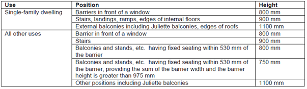
For buildings where likely users include children under five years of age, regulations state that there should not be gaps in balustrades which permit a sphere of 100mm to pass through.
Glazed barriers
Glazed barriers will require a nominated person to undertake a site specific design to ensure that the design of the guarding for the scheme is suitable and due diligence has been demonstrated. For glazed barriers there are four important criteria for the designer to satisfy:
A detailed design pack is to be submitted to demonstrate how these criteria will be satisfied as part of the risk management process.
Drainage approaches
Drainage is defined in this context as the management for the dispersal of water. A form of water management is required on all balconies, regardless of their surface area which may be either:
Positively drained - water is collected on a waterproof surface and directed to a piped outlet into the wider drainage network. A method of warning occupants in the vicinity of the building where a blockage arises in a positively drained approach where water is collected through the use of a conspicuous overflow pipe.
Edge drained - a design approach which allows water to quickly pass through a pedestrian surface through to a soffit collection tray or impervious surface laid to falls where it is momentarily collected and drained away from the weatherproof envelope of the building so that it does not cascade onto another balcony and discharges to a lower level where the water is appropriately managed.
Free drained - where a free draining approach is used, water is not collected on a membrane or impervious surface, such as a soffit collection tray but designed to instantly dissipate through a number of perforations in the balcony substrate to atmosphere so that it does not cause a risk of water ingress to the weatherproof envelope.
Products where proposed, are to be provided with 3rd party accreditation and used appropriately according to the proposed drainage approach employed. Materials where specified to provide a certain level of durability may require additional verification certification to demonstrate the required level of performance will be achieved to meet the Functional Requirements of the Technical Manual.
Balcony types
These different approaches are only suitable based on the type of balcony proposed. These are outlined in detail as follows.
1. Inset or semi-inset balcony drainage
Requirements
[1] Although a zero falls approach may be desirable, this can be challenging due to the requirements of Regulation 7 of the building regulations. In a zero falls arrangement typically the weight of the insulation supplied is used to compress water to encourage its dispersal to the outlet. Where insulation is not provided as it is not a heated space, or required to be of a lighter non-combustible material the action is reduced or lost and so the system cannot be effective.
[2] Where two outlets are specified rather than one outlet and one overflow or warning pipe it will not be clear that in the event of blockage that maintenance of that blockage is required. Without this warning, the likely cause of the first blockage may cause a follow on to block the second and resultantly cause both outlets to block, resulting in risk of water damage to the home. Resultantly an outlet and an overflow is the recommended approach.
Recommendations for inset or semi-Inset balcony drainage
The below diagram is one which demonstrates how the principles in this guidance could be applied to produce an acceptable design for an inset balcony:
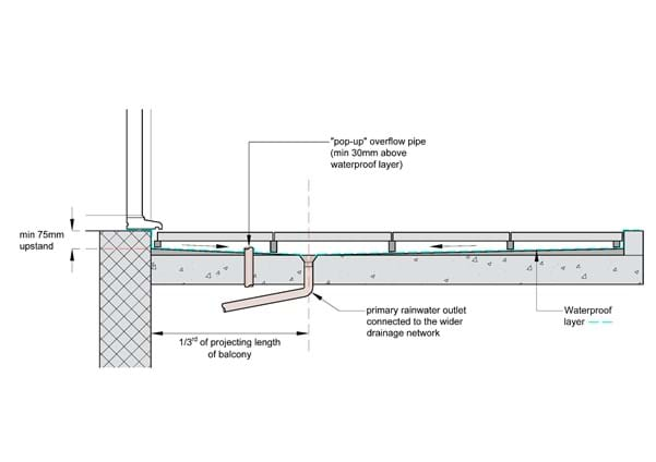
Red line shows 1/3 of projecting length of balcony. Details relating to pedestrian surface and guarding omitted for clarity.
Yellow denotes upstand. Mitre approach above may assist the designer to minimise build up height for falls.
The outlet should not be positioned adjacent to the threshold. It is recommended that the outlet is positioned at any point between the leading edge and 1/3 of the length of the balcony from the threshold as per the below detailing.
A conspicuous overflow should be provided. It is recommended a “pop up” overflow pipe protruding 30mm above the waterproofing layer is provided. It should be positioned in the zone between the threshold and 1/3 of the projecting length along the balcony. It may be offset to the side. The ‘telltale;’ overflow should discharge to the balcony below to allow for notification of the building management that the primary outlet is blocked. The capacity of the overflow should be not less than that of the outlet. Over flows should be positioned as close to the outlets as possible to avoid rainwater build up on roofs.
Piped or weir perimeter overflows can be acceptable but will not in many circumstances necessarily provide clear and immediate warning to a building user a blockage has occurred.
Where two falls intersect, a minimum finished fall of 1:80 along the mitre should be provided to prevent backfalling.
In the event it is proposed, the use of a stack which has breaks to allow water to flow into an open hopper at each level is to be carefully considered on a case by case basis, as a drainage approach as these outlets risk blockage without proper maintenance. Careful siting of these outlets is critical to the acceptability of this approach to mitigate this risk.
2. Projecting balcony – edge drained
Where a balcony which fully projects from the thermal envelope of the building is specified, positively drained, edge drained or free drained approaches may be employed. Although the Functional Requirements may be met with regard to meeting the minimum standard with the scope of a latent defects structural warranty, it is for the designer to consider the advantages and disadvantages of these approaches and the potential impact to those in and around buildings.
Requirements:
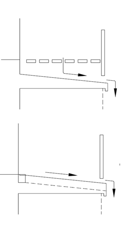
Figure 1 - Examples of acceptable drainage approaches for projecting balconies.
3. Projecting balcony - free draining
Where a free draining approach is used, water is not collected on a membrane or impervious surface but allowed to dissipate through a number of perforations in the balcony substrate, meaning that any hydraulic head of water is avoided. The pedestrian surface is designed to ensure that water is not collected and stored in any way. The pedestrian surface and the water collecting surface are the same.
Requirements
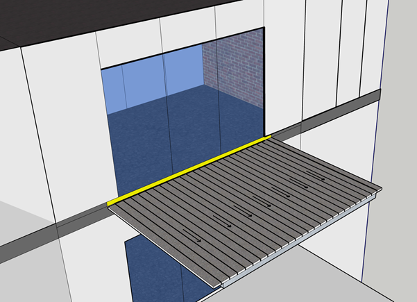
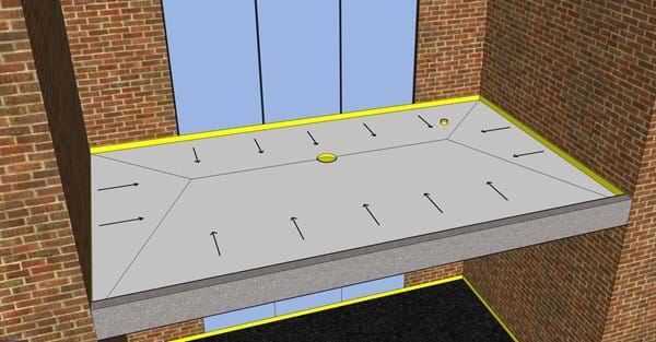
Figure 2 – Yellow denotes upstand. Details relating to non-combustible pedestrian surface and guarding omitted for clarity.
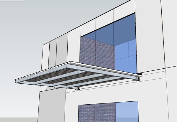
Figure 3 - Underside view (as figure 2 above, details have been removed for clarity)
Quality assurance and record keeping system should be provided at pre-construction to ensure that standards of workmanship can be demonstrated throughout installation.
Testing and final inspection
For all balconies, prior to request for acceptance it is good practice to test the operation of the balconies with a ‘bucket test.’ This is where a bucket of water is poured over the surface of the balcony and adjacent to the threshold of the door and the outcome recorded to ensure proper operation of the outlet and the overflow where appropriate. Although the volume of water will be greater than in operation, it will show the effectiveness of the drainage approach including drainage paths and highlight any issues relating to the drainage, such as backfalling occurring. It is recommended that this is included in the site Inspection and Test Plan.
Where a waterproofing product such as a membrane or coating has been provided, additional testing may be requested such as peel tests to ensure sufficient bonding has taken place between the substrate and the waterproofing product.
The site team should check the all elements, including the guarding, pedestrian surface and door sills complete for each plot prior to requesting final inspection.
The developer should have in place an Operation and Maintenance manual (O&M) and should identify:
Manual to the Building Regulations
The Building (Amendment) Regulations 2018 http://www.legislation.gov.uk/uksi/2018/1230/made
Approved Document B: Approved Document B (fire safety) volume 1: Dwellings, 2019 edition incorporating 2020 amendments
Approved Document K: protection from falling, collision and impact https://www.gov.uk/government/publications/protection-from-falling-collision-and-impact-approved-document-k
BS 8579:2020: Guide to the design of balconies and terraces
BS 6180:2011: Barriers in and about buildings - Code of practice
BS 8204-3:2004 - Screeds, bases and in situ floorings. Polymer modified cementitious levelling screeds and wearing screeds - Code of practice (+A2:2011)
FeRFA Guidance Note: No 15 https://www.ferfa.org.uk/wp-content/uploads/2018/07/TGN15GuidetoScreedsAugust2017-RIBAApproved.pdf
Liquid Roofing and Waterproofing Association – Guidance Note No. 3 - Generic Types of Liquid Applied Waterproofing Systems, For Roofs, Balconies and Walkways
Liquid Roofing and Waterproofing Association – Guidance Note No. 4 Roof, Balcony and Walkway Refurbishment Using Liquid Applied Waterproofing Systems
Liquid Roofing and Waterproofing Association - Hot Melt Code of Practice - Specification and Use of Hot Melt Monolithic Waterproofing Systems for Roofs, Balconies and Walkways
Read more articles on the Resource Hub and sign up to receive our blog round-up.
Every care was taken to ensure the information in this article was correct at the time of publication (March 2022). Guidance provided does not replace the reader’s professional judgement and any construction project should comply with the relevant Building Regulations or applicable technical standards. For the most up to date Premier Guarantee technical guidance please refer to your Risk Management Surveyor and the latest version of the Premier Guarantee Technical Manual.
Reference: TS 3174