Download a PDF version of this article.
Flat roofs are often subjected to temporary standing water, or ponding, especially during or following a heavy downpour of rain. There are various narratives regarding the levels of acceptability and the stated impacts on the waterproofing system will vary from various manufacturers. However, from a Warranty position, the effects of temporary standing or ponding areas of water are explained below.
Rainwater should flow over the roof area as a relatively thin surface film, perhaps only a few millimetres deep dependent on the length of the run to the outlet, the texture of the roof surface and the fall.
Where this is slowed by whatever means, e.g. inadequate fall, or no allowance for deflection, this can result in the collection and longer term ponding of rainwater on the roof.
For warranty purposes:
1. A full set of detailed drawings including:
a) Roof plan showing direction of falls and position of outlets and overflows
b) Sections showing roof build up and how falls are to be created. Sectional details should show all components to be used in flat roof build up (insulation type and thickness, vapour control layer, waterproofing membrane/layers etc.
c) Site specific detailing for all junctions, outlets and penetrations
2.Details of all components to be used in the construction of the flat roof should be provided
3. Engineers drawings and calculations for the roof structure
4. Third party accreditation for the waterproofing membrane/layer
5. Details of all fixings, their frequency and fixing method, including those for insulation and surfacing. Fixing methodology should be supported by appropriate wind uplift calculations.
6. Details of all fire stopping which should include specification and a detailed location layout drawing showing positioning of all fire stopping.
7. Outline of method and plan for testing the integrity of the waterproofing layer.
8. A flat roof membrane manufacturer’s approved installer must be used for all flat roof coverings. Evidence of the manufacturer’s approval of the contractor to install their products should be provided to the warranty surveyor.
9. A roof deflection analysis should be provided for medium to large roofs, those with complex roof layouts and for any roof areas that carry items of plant or are subject to access provisions beyond periodic maintenance of the roof area.
The warranty surveyor, at their discretion, may also request supporting information that demonstrates suitability for use of any materials or systems contained within the above.
Flat roof areas that are being subjected to ponding water will have an increased risk of:
Water penetration – punctures of a roof membrane are an issue irrespective of their position. However, if the roof should be punctured or damaged in a ponded area, standing water can build a head of pressure which can facilitate faster water flow into the building below as well as damaging the structure.
Progressive deflection of the deck – the effect of ponding water creates an increased loading. As the depth of ponding water increases, more weight is applied and the deflection increases. This continues until damage occurs to the deck or remedial work is taken to alleviate the issue.
Outlet blockages – ponding water facilitates the build-up of dirt, leaves and algae. Any loosening of the detritus will then flow to and obstruct outlets, increasing the potential for further ponding.
Freeze/thaw impact on flat roof coverings – an area of water that freezes will reduce any flexibility of the membrane. During a thawing period, areas unaffected by standing water will move in response to the rise in temperature, however areas under frozen water will respond more slowly. If this occurs on a lap in the membrane, it can force open the joint and allow water into the building fabric.
Diminished access provision – areas under water give rise to a lack of access for maintenance of both the roof and any plant mounted upon it.
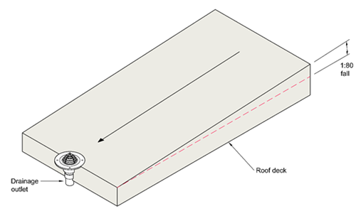
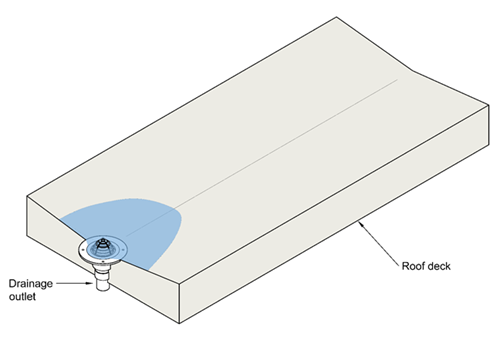
Areas with incorrect falls – it is normal practice for a flat roof, having a pitch not greater than 10°, to have design falls of 1:40 which achieve 1:80 in service. This allowance is given to allow for site inaccuracies and minor deflections in the deck. Resultantly where this final 1:80 is not achieved, ponding water can occur. The image below illustrates the achievement of correct falls to the outlet.
Raised outlets – where outlets are positioned close to supporting structure e.g. outside walls, columns or internal load bearing walls, a natural deflection at deck mid span can result in the outlet being higher than the main area of the roof which creates an area for ponding to occur.
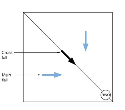
Cross falls – at the junction of two roof surfaces with different directions of fall, a valley will be formed, known as a cross fall. The effective slope created at the cross fall will be less than that of the main roof falls. As an example, where a main roof fall achieves 1:80, the cross fall will only achieve 1:113. The cross fall must achieve 1:80 as a minimum.
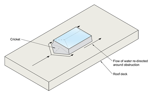
Interrupted falls – the position directly behind roof lights often gives rise to the opportunity for slowed drainage or drainage ‘dead spots’ where water ponds due to interruption of the roof fall. Drainage crickets are double triangle structures, constructed in the deck or sometimes provided by insulation to divert water around obstructions. Where these are not supplied, ponding will often occur.
Blocked outlets - outlets that become blocked will result in slowed or obstructed flow from the roof. This can lead to water backing up around the outlet. This can often be caused by site debris that collects around drain guards.
Consideration to access for maintenance of outlets must be made by the designer for the end user, post completion, especially where risks of debris can occur e.g. from trees or windblown sand (Coastal locations).
During the build process, trades temporarily affected by rainwater running from outlets on the outside e.g. where brickwork is being completed and rainwater pipes have yet to be fitted under outlets, will often block the outlet which can create a temporary ponding effect on the roof. It is therefore important to check all rainwater outlets are not blocked and are working to avoid this temporary ponding.
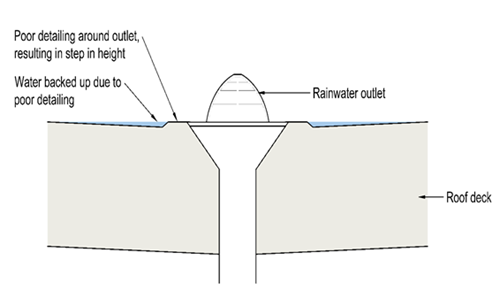
Incorrect outlet detailing - outlets that are set too high in relation to the finished surface of the roof covering will often lead to ponding water. This is often a result of the detailing around the outlet being carried out after the main roof area is complete. When this happens, the formed lap creates step in height. This can result in slowed water movement and a standing area of water that cannot naturally drain into the outlet. Plus, there is a potential for silt build up further adding to the problem.
Storm conditions – in instances where rainfall intensity increases over a short period e.g. flash flood conditions, the drainage capability of an outlet in normal circumstances can be rapidly reached and the water will pond over the area local to the outlet, creating a temporary natural sump. It should be noted that this will only occur for a few minutes during a storm until an equilibrium state is reached and the water discharge down the outlets matches the rate of water arriving at the outlet. Correctly calculating the expected flow to the outlet and its capacity in accordance BS EN 12056-3 should ensure that any temporary build-up of water is reduced to a minimum.
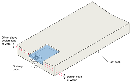
Sumps and gutters – during a storm event these will fill extremely fast until the design head is reached. Once the equilibrium state is reached, with the water discharging down the outlets to match the rate of water arriving, sumps and gutters should then be free of standing water. The depth of a sump or gutter should be 25mm above the design head of water. Ponding water should not overtop the defined edge of the sump or gutter and spill out onto the roof slope.
Roof areas should be free draining and ponding water must be avoided.
At practical completion of the roof, a thorough recorded visual inspection should be carried out with representation from the General Contractor and Roofing Contractor in attendance. In instances that the warranty surveyor determines that ponding water is present, an independent roof drainage assessment including a level survey must be conducted by a suitably qualified professional to determine what remediation measures are required.
It is important to note that this assessment should not include flood testing as a method of demonstration of the suitability of drainage because flood testing of flat roofs can place a higher load on weak areas of the roof covering, and if there are defects, could create more damaging consequences if water penetrating internally results. Other test methods are discussed in the ‘Roofs’ section of the Technical Manual.
The testing service provider should provide evidence of the following:
Read more articles on the InSite and sign up to receive our blog round-up.
Every care was taken to ensure the information in this article was correct at the time of publication (June 2023). Guidance provided does not replace the reader’s professional judgement and any construction project should comply with the relevant Building Regulations or applicable technical standards. For the most up to date Premier Guarantee technical guidance please refer to your Risk Management Surveyor and the latest version of the Premier Guarantee Technical Manual.
Ref: TS-3242